The First Ignition Method
The first MA lamp had only two electrodes, simply to sustain the main arc and nothing else. To cause the initial breakdown in the discharge tube and ionise the gas filling a high voltage gradient is always required, the precise voltage depending on fill pressure of the argon gas, and on the ratio between the length and diameter of the discharge tube. Naturally the argon pressure is chosen to give the lowest breakdown voltage, and although the length to diameter ratio is quite low for MA lamps, the effect of wall charges means that the ordinary mains voltage is not high enough to strike the discharge on its own. In practice, most 400W MA lamps would require a pulse of 300-500V to initiate the discharge if no auxiliary method was employed to lower this value. In the first experimental installations of MA lamps the voltage pulse was provided by a small Tesla coil included in the control circuitry. The method was crude though and the incorporation of a Tesla transformer into each lighting fitting would have added great expense and inconvenience, so it was superseded in readiness for the first commercial installation with MA Mercury lamps.
The Internal Auxiliary Electrode
By locating a third small electrode in very close proximity to one of the main electrodes, the striking voltage of the lamp can be considerably reduced by virtue of the fact that the gap between these two electrodes is small, so the voltage gradient between them is high and the gas filling is easier to break down. The standard method is to include a simple tungsten or molybdenum wire directly beside the main electrode at the cap end of the arc tube. This is connected via a high resistance (approximately 50 kW) to the main electrode at the opposite end of the tube. The principal of operation is exactly the same as for the self-starting Cooper-Hewitt lamps already described. In the MA case however, the starting electrode is inside the arc tube so no high voltage kick is required - ionisation between the main electrode and the adjacent auxiliary takes place at normal operating voltages, the lamp striking voltage being lowered to as little as 100V in some cases. There is more than enough safety margin between this and the usual 240V mains supply voltage to ensure that ignition will always take place even during dips in the mains voltage, in colder atmospheres or later in lamp life when the striking voltage always tends to rise by a small amount.
A small glow discharge is easily initiated between the starting electrode and the main electrode beside it, the discharge current being limited to approximately one thousandth of the normal lamp current by the resistor. Once ionisation has taken place in the vicinity of the auxiliary electrode, the tube becomes conducting and the arc moves almost instantly across the two main electrodes, because there is no resistance in this path. The same principle continues to be employed in all modern mercury and many metal halide lamps as well. A diagram of the self-starting MA arc tube and the wiring arrangement to the auxiliary electrode is shown in Figure 26.
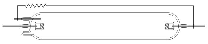
Figure 26 - Self-Starting MA Arc Tube with Internal Auxiliary Electrode
The External Auxiliary Electrode
In the early days, the inclusion of a third auxiliary electrode was seen as rather tedious, adding cost and technical complexity to the lamp with the added chance that owing to the presence of an extra glass-to-metal seal, cracking of the arc tube was more likely resulting in an unreliable lamp design. Many experiments were therefore conducted with external starting electrodes, British Siemens and GE of America being the principal investigators of this field.
In the most simple designs, a few turns of thin wire were looped around one end of the arc tube and connected to the electrode at the opposite end. One of the first Siemens designs is illustrated in Figure 27. Later this was improved upon by passing a thin strip of wire mesh around the outside of the tube and welding it to the arc tube support frame, which was connected to the main electrode at the opposite end.

Figure 27 - Self-Starting MA Arc Tube with External Auxiliary Electrode
The effect of this was to neutralise the so-called 'grid effect' caused by wall charges on the arc tube that normally kept the striking voltage higher than would be expected, and the external electrode was able to produce ionisation inside the discharge tube due to the capacitance between this and the internal main electrode. This very considerably reduces the required striking voltage to a level which is usually attainable from the mains electricity supply. However at ordinary mains frequencies of 50-60Hz it is not completely effective, the internal electrode remaining much more reliable. Consequently the external starting electrode was only widely used for lamps which were operated on a high frequency supply such as the MBM Coal Mining lamp, or on lamps designed for operation on a high supply voltage as in the case of Philips' first MB lamp.
The table below identifies the difference in striking voltage for 400W MA/V lamps equipped with internal and external striking electrodes at two different temperatures. It is clear to see that the internal electrode is much more effective. While the striking voltage of the external electrode is suitably low at normal temperatures, on cold days or with aged lamps this method may prove troublesome.
| Temperature,°C |
Internal Probe Striking Volts |
External Electrode Striking Volts |
| 16 |
125 V |
170 V |
| -12 |
165 V |
300 V |
Table 2 - 400W MA Striking Voltages for Internal / External Starting Electrodes |